AI-Driven Segmentation on Weight Bearing CT Introduction Accurate segmentation is critical for orthopedic workflows, including…
A Novel Anteroposterior Axis of the Tibia for TKA: A WBCT Analysis
Key Points:
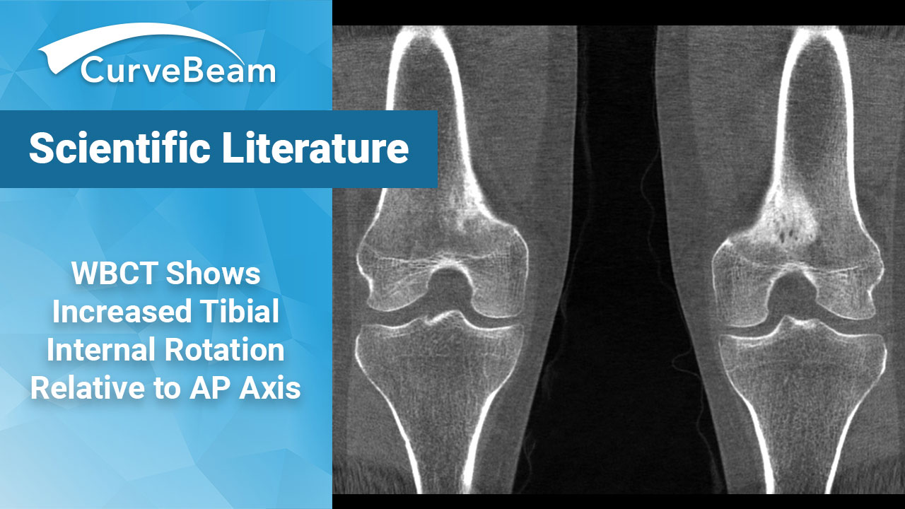
- On weight bearing CT (WBCT) scans of healthy subjects, the AP axis was found to be positioned in 7.4 degrees of internal rotation relative to the traditional AP axis measured on supine CT scans.
- Researchers concluded WBCT clearly showed the effects of full weight bearing on the femorotibial rotation position.
- Any systems that may require awkward standing positions during scanning will not provide the best results.
In total knee arthroplasty (TKA), the rotational alignment of the tibial component substantially affects patellofemoral kinematics, patient-reported outcome measures, as well as durability of the implant due to the patellofemoral rotational mismatch which can increase the Q-angle and decrease muscle strength in the quadriceps.
The surgical transepicondylar axis (SEA) is used as a landmark of rotational alignment of the femoral component since the SEA has been believed to represent the flexion-extension axis of the knee in mechanically aligned TKA. The current standard of care utilizes “Akagi’s line”, a line which passes through the middle of the posterior cruciate ligament (PCL) and the medial border of the patellar tendon attachment, as a confident landmark of the anteroposterior (AP) axis of the tibial component. This method works because the AP axis appears perpendicular to the SEA on supine computed tomography (CT) under knee extension.
Dr. Ryo Sasaki et al. of the Department of of Orthopaedic Surgery, Keio University School of Medicine, Tokyo, Japan, hypothesized that this measurement may be different when comparing non-weight bearing CT (MDCT) scans to weight bearing CT (WBCT) scans. Their study results confirmed that on WBCT scans, the AP axis was positioned in 7.4 degrees of internal rotation relative to the traditional AP axis.
Materials and Methods
The study compared a total of 43 knee joints in 23 healthy patients. Exclusion criteria included anyone with a history of knee injury, developmental abnormalities including patellar hypoplasia and discoid lateral meniscus, or a history of tibial tubercle apophysitis. WBCT and MDCT images were obtained for all patients.
To match the coordinate systems between the weight bearing and non-weight bearing 3D surface models for each patient, the tibia was matched using the iterative closest-point algorithm. The coordinate system was then applied to the tibia using the method defined by Enomoto et al. The Y-axis (vertical) was defined as the line connecting the midpoint of bilateral tibial eminences and the apex of the tibial plafond. A line was formed connecting the medial margin of the proximal end of the tibial tuberosity and the center of posterior intercondylar notch proximal to the enthesis of the posterior cruciate ligament at the level of the lateral joint space, and the X-axis was the projection of that line onto a plane perpendicular to the Y-axis (Akagi’s line). The Z-axis was defined as a line perpendicular to both the X- and Y-axes.
Using 3D surface data of the femur for each condition under which the medial and lateral epicondyles could be recognized clearly, the SEA was determined to connect the sulcus of the medial epicondyle to the lateral epicondyle. The SEA was projected on the X-Z plane, and the straight line perpendicular to the projected SEA was defined as the upright weight bearing axis or upright non-weight bearing AP axis. The angle between the X-axis (Akagi’s line) and each newly defined AP axis was calculated. Angular differences between the non-weight bearing and weight bearing AP axes were calculated and defined as the change in femorotibial alignment due to weight bearing in the standing position. Finally, using 3D surface data of the femur and patellar tendon, the attachment of the patellar tendon to the tibia was identified, and the tibial tuberosity was defined as the maximum width of the attachment in the X-Z plane.
Results
The newly defined WBCT AP axis was positioned in a mean of 7.4 +- 4.3 degrees of internal rotation relative to the traditional AP axis. Mean distance between the Akagi’s line and the WBCT AP axis at the edge of the tibia plateau was 2.9 +- 1.6 mm. The defined WB AP axis started at one-seventh of the tibial tuberosity away from the medial border of the tibial tuberosity. The non-weight bearing AP axis was positioned in a mean of 3.5 +- 4.1 degrees of internal rotation relative to the traditional AP axis. The mean change in femorotibial alignment due to weight bearing in a natural standing position was 3.9 +- 4.1 degrees of femoral internal rotation relative to the tibia.
Conclusion
The study concluded that WBCT clearly showed the effects of full weight bearing on the femorotibial rotation position and supported the researchers’ initial hypothesis that the tibial AP axis in weight bearing position would differ from the traditional non-weight bearing AP axis.
Researchers stated that weight bearing AP axis is about 7.4 degrees internally rotated relative to the traditional non-weight bearing AP axis, at about one-seventh of the tibial tuberosity away from the medial border of the tibial tuberosity.
It was noted a similar study by Hirschmann et al. looked at the femorotibial rotation of symptomatic knees under upright weight bearing conditions. That study found that the tibial AP axis in the axial plane was in 3-degree internal rotation relative to that in the supine position. A major limitation of this study, however, was that the system required patients to put their foot in into a small gantry and set their contralateral foot aside or stabilize their body using supportive tools such as a pole. Therefore, the authors discounted how accurately Hirschmann was able to accurately portray true weight bearing or a natural standing position.
To read the full study click here.
Related Posts